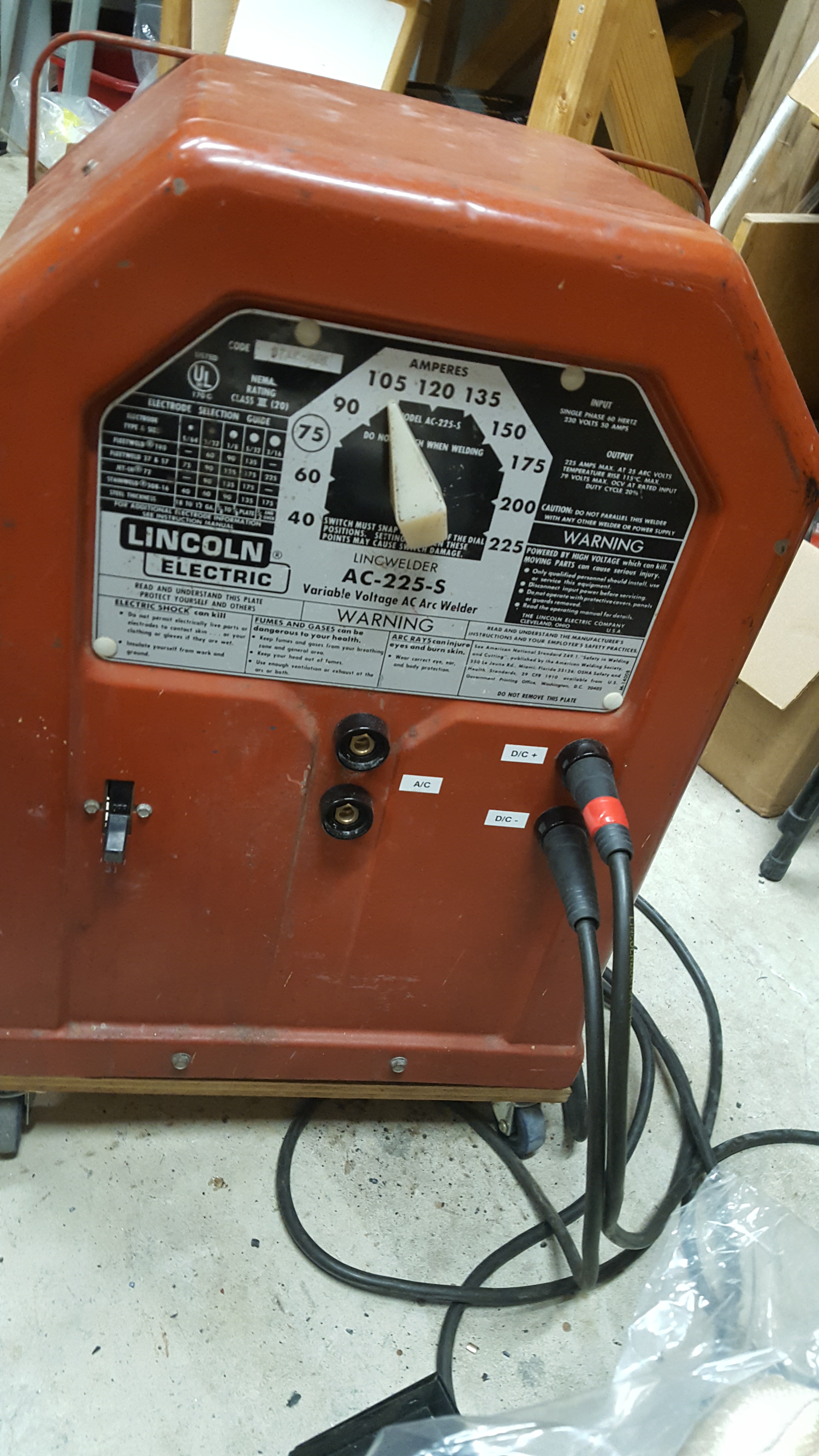
AC-225 Welder Amperage Control with SCRs
In an attempt to make my AC-225 decent at TIG welding, I added an amperage control circuit. This allows me to plug in my homemade foot pedal and fine tune the arc as I’m welding. Like most of my AC-225 modifications, most of the credit goes to Gregory Hildstrom for all the work he put into making this circuit and the other modifications he wrote about. The other person who deserves much credit is Mike W who posted the original diagram.

Sources
I tried to understand how the control circuit I used works so the first few links go into how SCRs can control current and some basic control circuits. The rest are similar to or the same circuit that I used.
SCRs Theory and Circuits:
https://www.youtube.com/watch?v=9rXpXwuCOG8
Silicon Control Rectifier SCR Basic AC Circuit:
https://www.youtube.com/watch?v=45H4J_S52Y4
Mike W’s Photobucket album with his original diagram:
http://smg.photobucket.com/user/tek798/library/Welding?sort=3&page=1
In case his Photobucket goes down, I saved the relevant photos to a gallery here for posterity’s sake:


Gregory Hildstrom’s article on making the circuit:
http://hildstrom.com/projects/ac-225/index.html#footpedal
Discussion of the original Mike W design and modification to insulate the foot pedal from the 240V with a transformer (I did not do this, but my foot pedal is made of wood and if something shorts, I probably won’t die. YMMV):
Arc Welder output Current Control and DC Rectifier Upgrade:
A pretty cool similar setup mounting everything on the rear vents that uses a slightly simpler circuit:
http://shopfloortalk.com/forums/showthread.php?t=25420
Building the Circuit
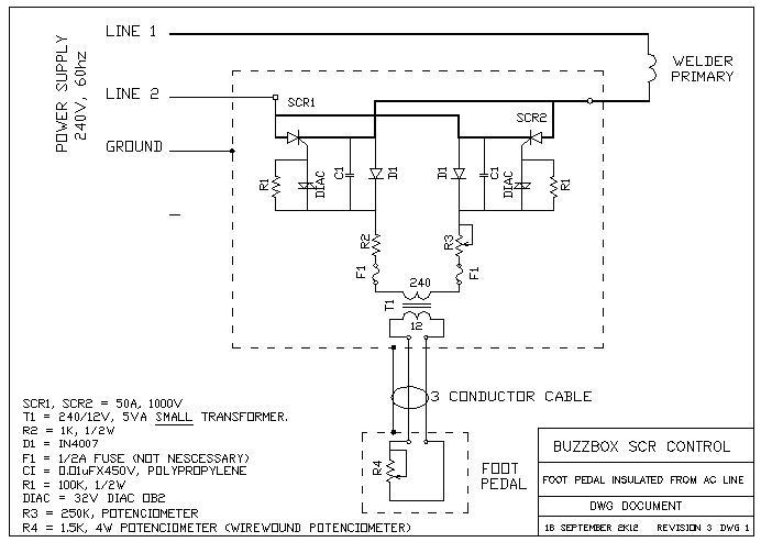
The circuit diagram is essentially the same as Gregory Hildstrom’s. I don’t want to blatantly rip off his diagrams, so I suggest checking his site out to see it and I’ll sketch up my own. I’ve made a few changes and maybe my photos will help if someone else is making this.
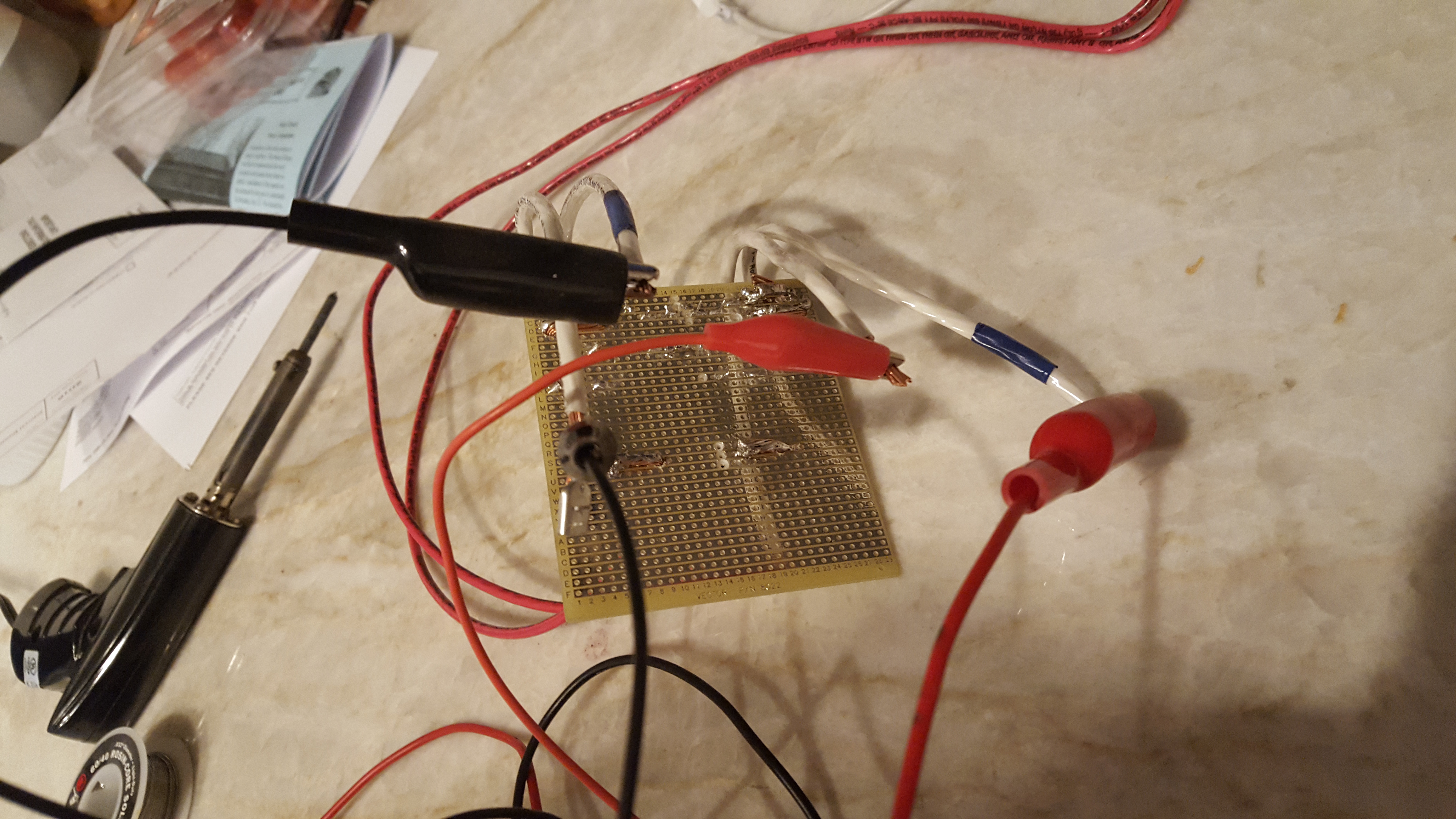
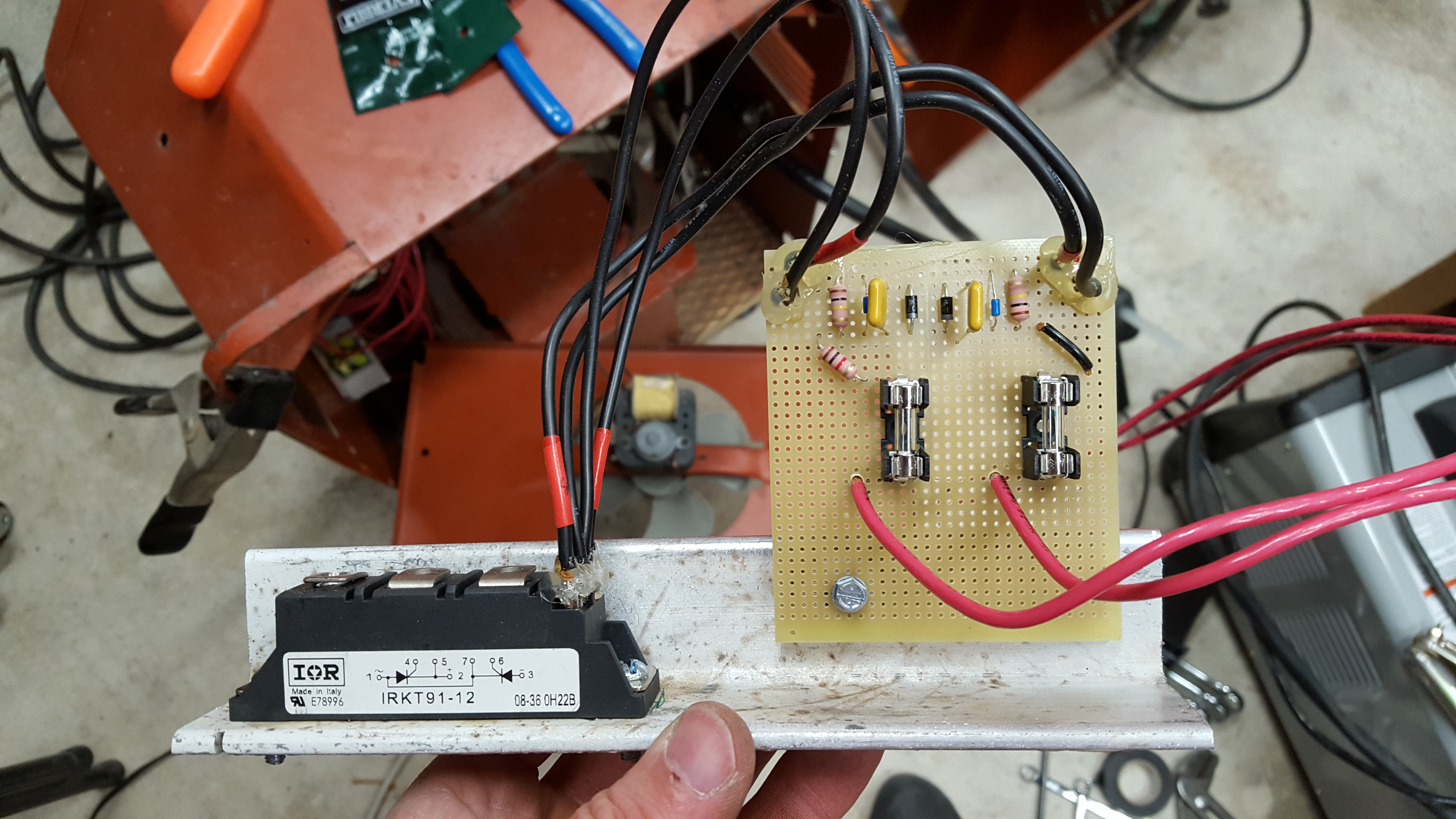
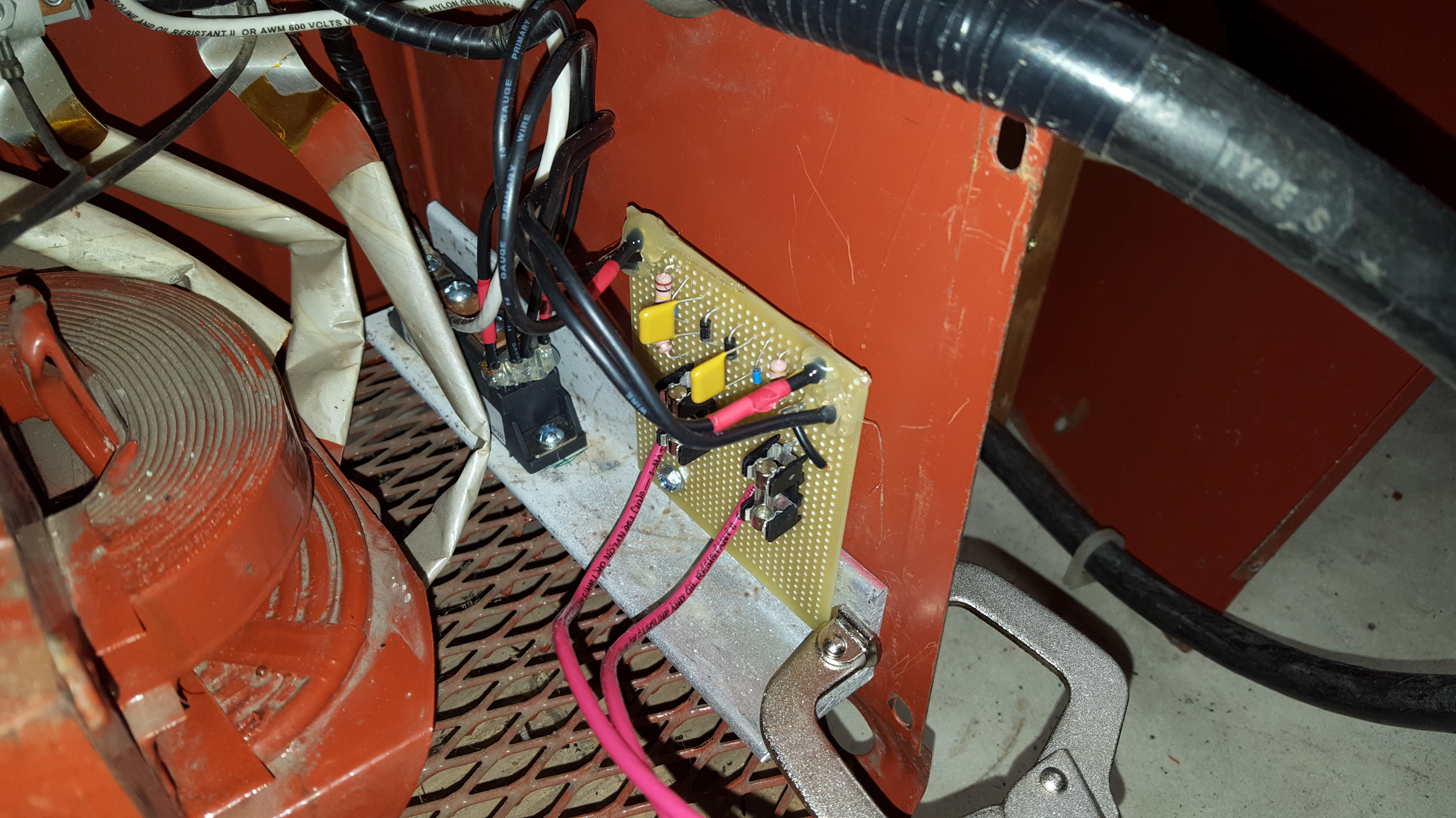
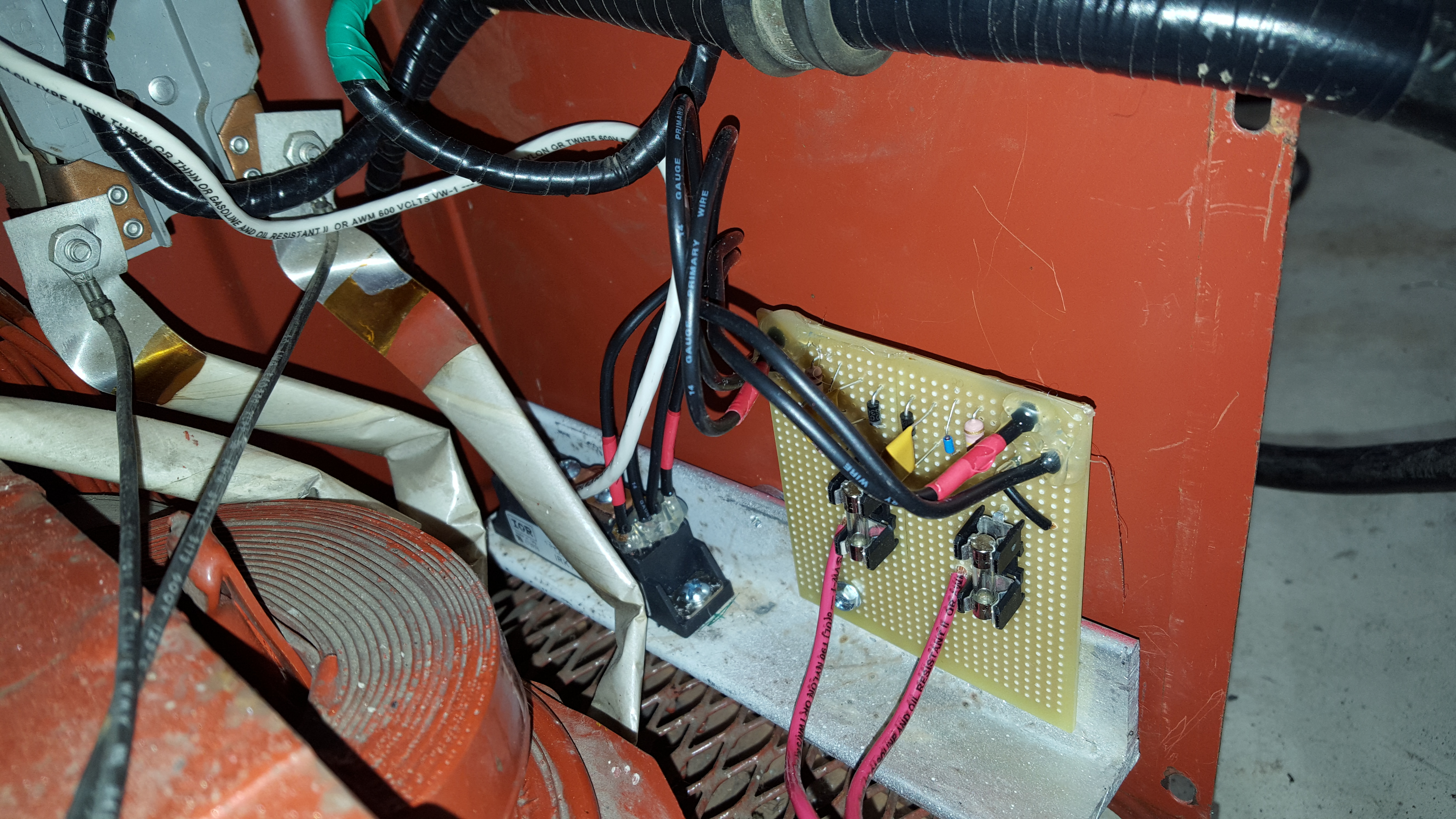
The circuit is built on a 3″ x 3.5″ PCB with strips. I ordered all the parts from Digikey for a total of $55. After putting it together, I searched around and could have saved about $30 by getting the 470K potentiometer and the capacitors from eBay. My soldering skills aren’t very good but after testing everything, I didn’t find any shorts and it all seemed to work. I mounted the PCB and SCR on a piece of heavy aluminum angle I had leftover to act as a heatsink.
After making some more circuits, I suggest using PCB screw terminals instead of soldering the leads directly to the board. I would also design a PCB and get it made for a few dollars with Fritzing and a company like Allpcb.com.
I’ve linked to the cart if you want to see all the parts from Digikey: http://www.digikey.com/short/3n5qq3
Or if you want a spreadsheet of the parts: AC225 Amperage Control DigiKey Spreadsheet

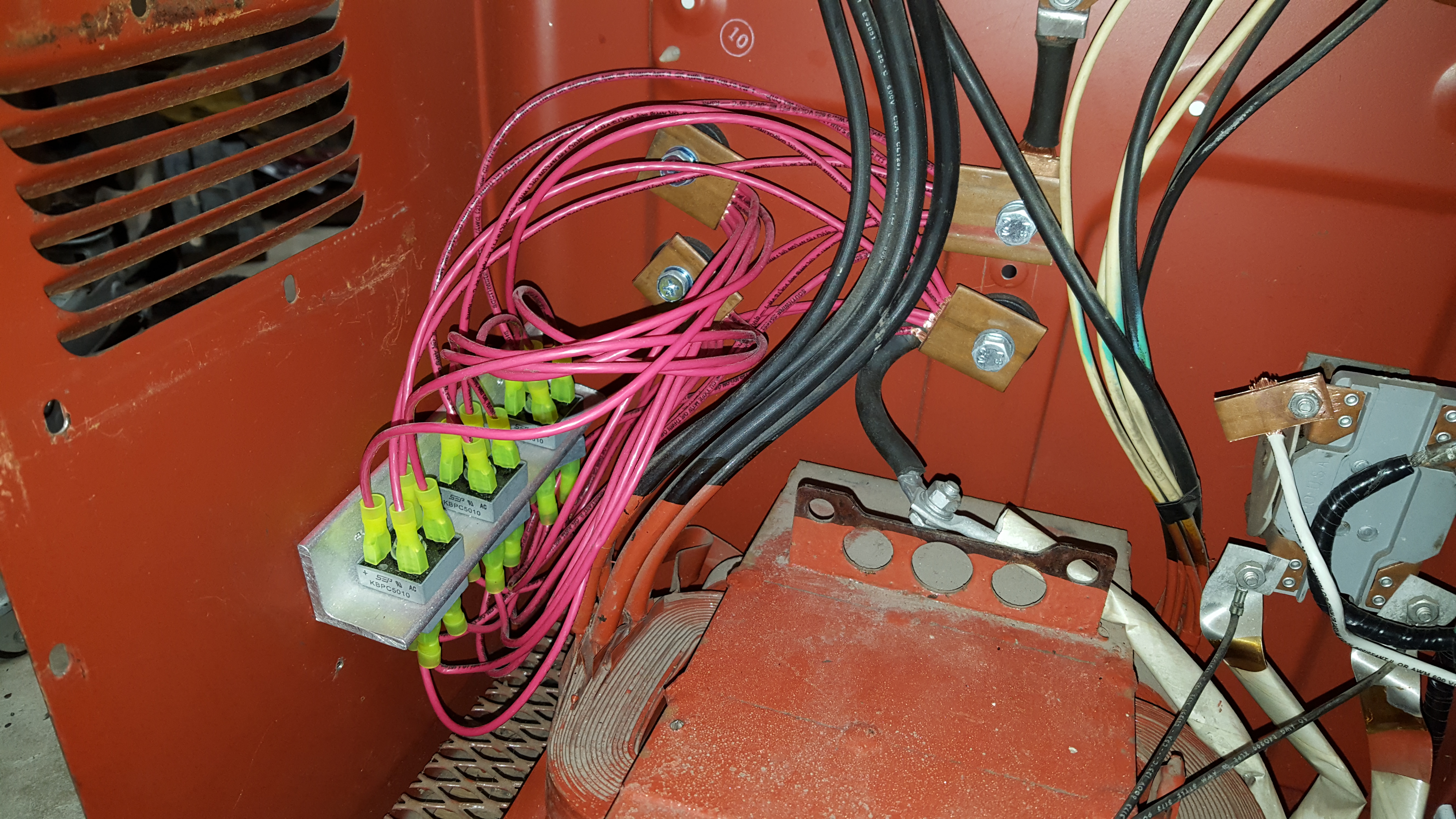
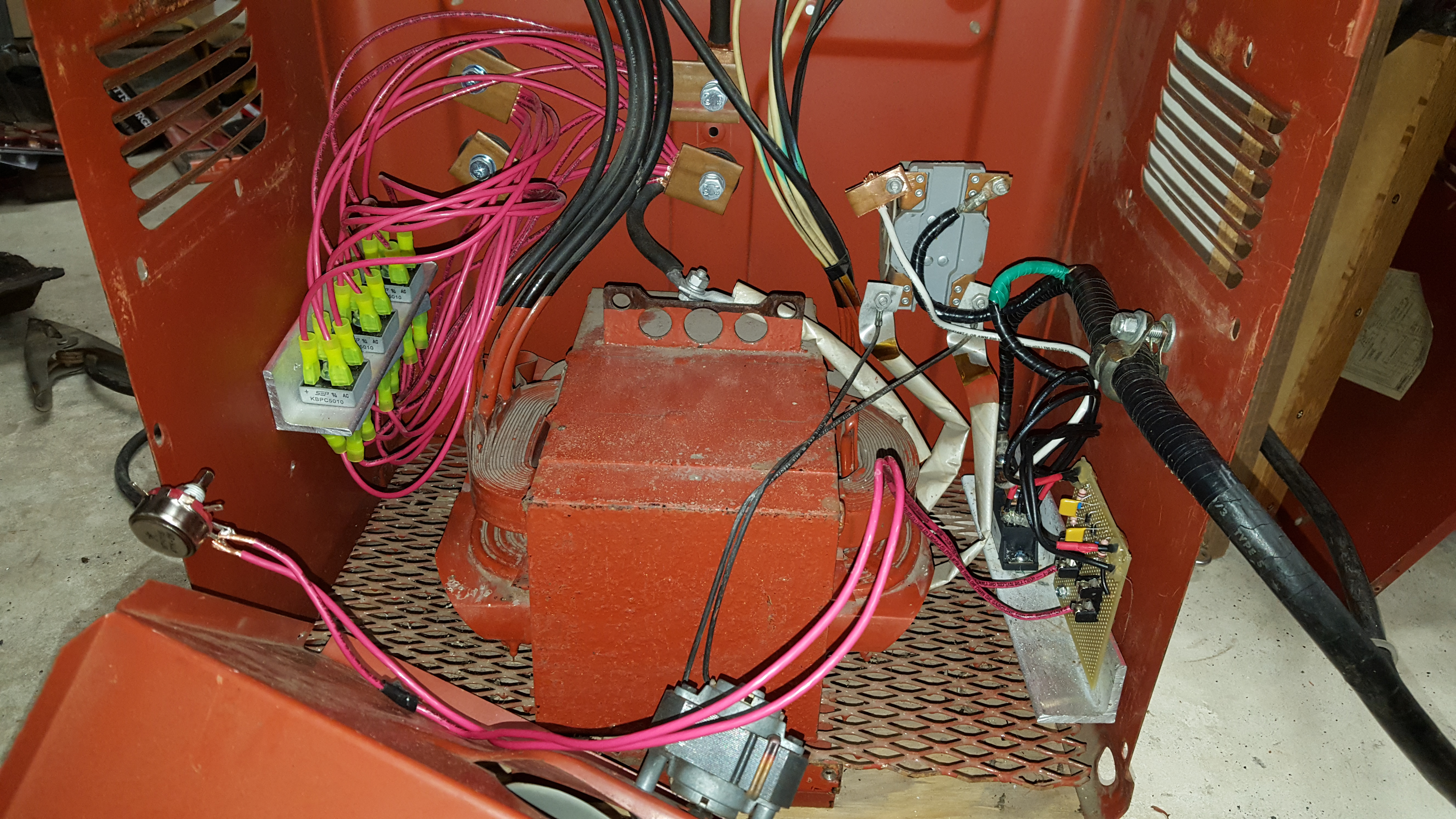
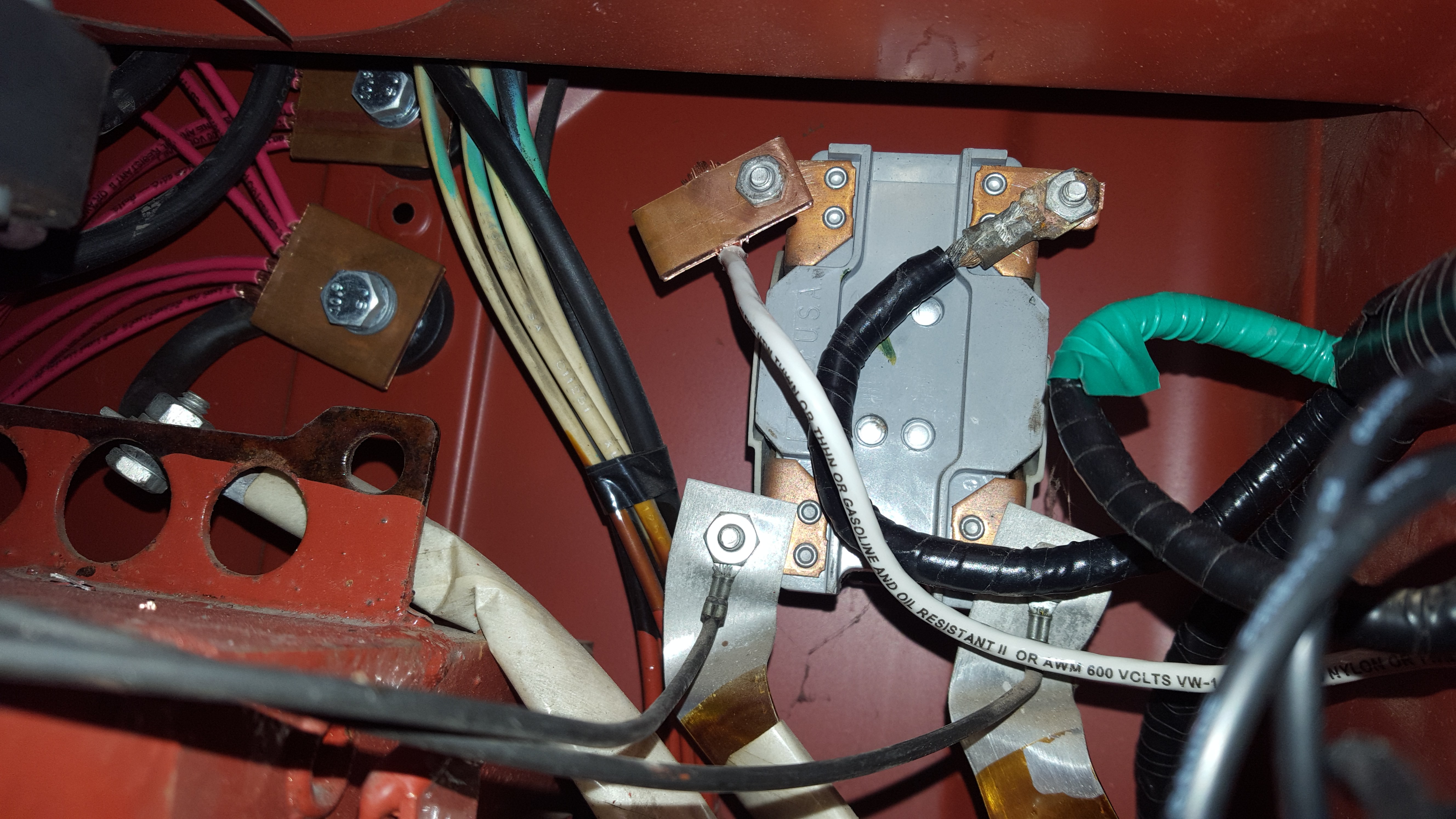
Installing the Circuit
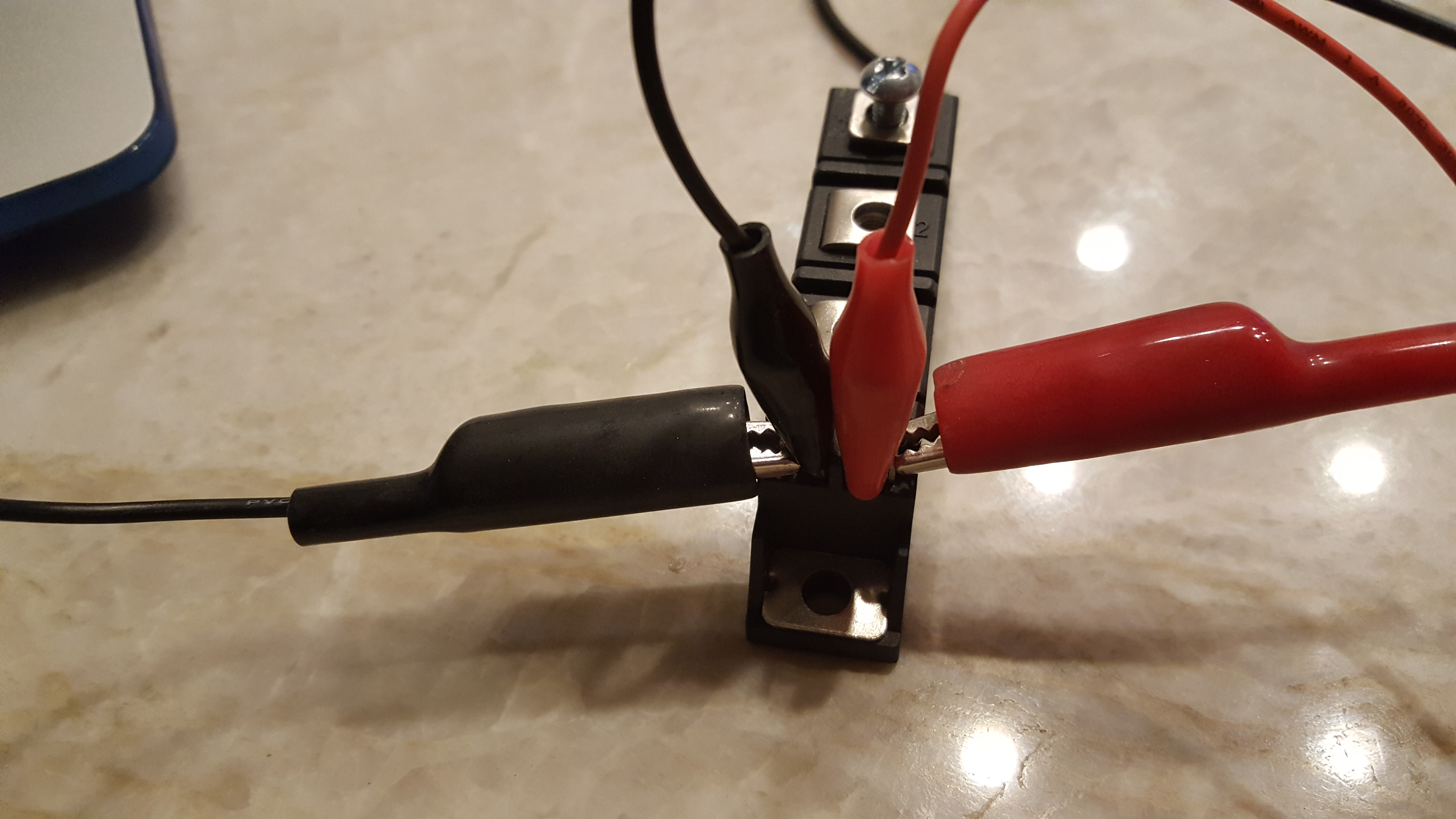
The aluminum angle was screwed into the side of the case near the power cable and one of the power cables was disconnected from the switch and into the SCR on connector 1. On the SCR the 2 and 3 get bridged and then gets plugged into the switch to complete the circuit. For testing, I soldered the potentiometer into the board and gave it a whirl. Shockingly it worked!


Installing the Amphenol Connector
I decided to break from Gregory Hildstrom’s design by not having a remote switch on the front panel. This is a little cheaper since the switch by itself is around $100 and the only downside is always needing to have a 470K ohm potentiometer of some kind plugged it to make the welder work. I made a foot pedal and will probably also make a hand control for when fine control isn’t needed.


With everything back together, the welder works fine and the amperage control works down as low as 15 amps. My foot pedal is a little finicky but the control is good.
Leave a Reply